


Flanges offer a mechanical means of joining pipes, fittings (elbows, tees etc.), and valves. Compared to welds, flanges are a non-permanent type of joint that can be easily assembled and disassembled (ideal for systems that require maintenance). Flanges are installed via welding, screwing, or lapping, and they are the second most popular joining method after welding.
When assembling a flanged joint, always use a full complement of clean, new high strength bolts ensure that the new bolting material strength properties exceed the calculated bolt stress values to be generated in making the piping connection.
Now we learn about if basics about Flange Terminology
Flange terminology
Flange terminology and nomenclature can be confusing due to the similar terms, definitions, and phrases that are used. To make the learning process easier, readers should clearly understand the following terms:
Flange types – refers to the flange design. Examples of flange types include the welding neck (weld neck), slip-on, socket weld, threaded, blind flange and lap joint type flanges. Flange types are selected based on the temperature and pressure requirements, and are identifiable by their geometry.
Flange faces – refers to the area used for sealing of the flange; a gasket is usually installed between the two opposing flange faces. Examples of flange faces include the flat, raised, ring-type joint (RTJ), lap joint, tongue and groove, and male and female designs.
Flange surfaces – refers to the condition of the flange face sealing surface. A flange face surface may be smooth, or serrated1. The smoothness of a flange face surface is defined by its Roughness Average (Ra) or Arithmetic Average Roughness Height (AARH).
So Here are the Few Instruction for Assembling a Flange Joint
1. Always use flat washers on both sides of the connection.
2. Tighten all bolts until finger tight and ensure that joint and gasket are correctly aligned.
3. Tighten the flange bolts with a calibrated torque wrench to the specified bolt torques. Note: For anti-seize compounds, the torque values will be different.
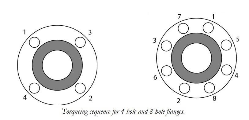
4. Tighten the flange bolts with a torque wrench; using a "crisscross" pattern that alternately tightens the bolts located 180 degrees apart. (see illustration below for 4 hole and 8 hole flanges.)
5. Using this pattern, tighten the bolts in 20% increments of the final bolt torque until 80% of final bolt torque has been achieved.
6. For tightening to the final torque values, tighten bolts sequentially clockwise once around the flange. This will help ensure that the bolts are evenly stressed.
7. Care should be taken to avoid over-torqueing, which can cause damage to the gasket and the sealing surfaces.
Note: When bolting together dissimilar materials, always tighten to the lowest recommended torque of the components in the joint. Using higher torques may cause excessive deformation of the "softer" material in the joint.
-page-001.jpg)


0 Comments